联系人:麦女士
手机:+86 15270269218
电话:
Q Q:3136378118
邮箱:stodcdcs@gmail.com
地址:江西省九江市瑞昌市东益路23号赛湖农商城401号


设图所示
在上面
根据所B板程序
图中的项目连接到:功能:
A车间供水
B车间排水选选项:
•二回水回路
•调节空气
图中的项目连接到:功能:备等备件
零件号:Art。编号注释
水和空DressPack/SpotPack
3HAC 17290-7节定义了内容
标准工具包!
电路图3HAC 17669-2 IRB 6600、6650和气装置见备件
零件部分!
有许多版本可用。
水和空气装置总成
包含所有必需的硬件
装配和连接
标准工具包,
7600使用气动焊枪
电路图3HAC 17669-1 IRB 6600、6650和
7600使用伺服焊枪
步骤说明/插图
1、确保电源
操纵器已关闭。
2
拧下其四个附件
螺钉。
如图所示
水和空气装置,见62页。
3、安装水和空气装置并固定
使用四个连接螺钉。
重新使用顶部后盖的螺钉。
4、连接供水和供气。在“水的连接”一节中规定
和64页的空气装置。
5、打开水和空气装置顶盖
通过拆除其连接螺钉。
如图所示
水和空气装置,见62页。
6、连接分线盒水电缆
和空气单元,在
水和空气装置。
xx0300000146
图中显示了水和空气装置
取下盖子。
部分:
•A:水中的分线盒连接
和空气单元XS101。
7、重新安装水和空气装置顶盖
并用附件固定
螺钉。
如图所示
水和空气装置,见62页。
2安装
2.7.1. 安装水和空气装置,SpotPack
64 3HAC 17667-1修订版:A
与水和空气装置的连接
下图显示了与操纵器底座的连接。
xx0300000058
下图显示了水和空气装置上的连接。
xx0300000145
盘子顾客
C车间压缩空气供应
D操作器基座上的PROC1压缩空气供应至
机械手
E PROC2在机械手基础回路中进水
2安装
2.7.1. 安装水和空气装置,SpotPack
3HAC 17667-1修订版:A 65
车间供水
以下步骤详细空气上的压缩空气适配器
单元
½”Parker pushlok编号39C82-15-8BK
2、推动90°Parker pushlok弯头
车间软管上的适配器
压缩空气供应。
3.如果未使用Parker pushlok软管,则使用
软管卡箍。
4、重新安装90°弯头阀(带
软管安装)安装在进气装置上。
5、固定空气阀连接器。参见13页说明了如何将水和空气装置连接到车间供水系统。
车间压缩空气供应
以下步骤单元
F操作器基座回水回路上的PROC3
G机械手基座上的PROC4
笔记只有这个位置
连接如
步骤操作信息/插图
1、松开手动水阀
用于水的入口和出口。详细介绍了如何将水和空气装置连接到车间压缩空气
供给
连接机械手和水和空气装置的软管
下面的步骤详细介绍了如何连接操纵器与水和空气之间的软管
2.将Parker pushlok适配器连接到
标有“车间供水”的软管
和“车间排水”。
½”Parker pushlok编号3D982-8-8BK
3.如果未使用Parker pushlok软管,则使用
软管卡箍!
4、重新安装手动水阀
(安装软管),在其各自的
位置:“进水口”和“出水口”。
5、固定水的连接器
阀门。
参见13页中的拧紧力矩
截面螺纹接头。
6、关闭手动水阀。
步骤操作信息/插图
1、松开90°Parker pushlok弯头
中的拧紧力矩
截面螺纹接头。
6、关闭手动压缩空气
阀门。
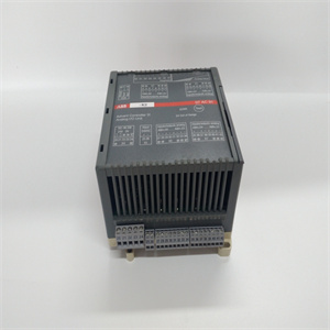
Equipment, etc. Spare part no. Art. no. Note Water and Air unit See the Spare parts section! A number of versions are available. The Water and Air unit assembly contains all required hardware for fitting and connecting Standard Toolkit, DressPack/SpotPack 3HAC 17290-7 The contents are defined in section Standard toolkit! Circuit Diagram 3HAC 17669-2 DressPack for IRB 6600, 6650 and 7600 using pneumatic welding gun Circuit Diagram 3HAC 17669-1 DressPack for IRB 6600, 6650 and 7600 using servo welding gun Step Action Note/Illustration 1. Make sure the power to the manipulator has been switched off. 2. Remove the top rear cover by unscrewing its four attachment screws. Shown in the figure in section Location of Water and Air unit on page 62. 3. Fit the water and air unit and secure it with the four attachment screws. Reuse the screws for top rear cover. 4. Connect the water and air supplies. Specified in section Connections to Water and Air unit on page 64. 5. Open the water and air unit top cover by removing its attachment screws. Shown in the figure in section Location of Water and Air unit on page 62. 6. Connect the split box cable for water and air unit with the split box at the water and air unit. xx0300000146 The illustration shows the water and air unit with its cover removed. Parts: • A: Split box connection at the water and air unit, XS101. 7. Refit the water and air unit top cover and secure it with its attachment screws. Shown in the figure in section Location of Water and Air unit on page 62. 2 Installation 2.7.1. Installation of Water and Air unit, SpotPack 64 3HAC 17667-1 Revision: A Connections to Water and Air unit The figure below shows the connections to the manipulator base. xx0300000058 The figure below shows the connections on the water and air unit. xx0300000145 A Plate customer B Plate PROC Item in figure Connect to: Function: A Shop water supply B Shop water drain C Shop compressed air supply D PROC1 on manipulator base Compressed air supply to manipulator E PROC2 on manipulator base Water in circuit 2 Installation 2.7.1. Installation of Water and Air unit, SpotPack 3HAC 17667-1 Revision: A 65 Shop water supply The procedure below details how to connect the water and air unit to the shop water supply. Shop compressed air supply The procedure below details how to connect the water and air unit to the shop compressed air supply. Hoses connecting manipulator and water and air unit The procedure below details how to connect hoses between manipulator and water and air unit. F PROC3 on manipulator base Water return circuit G PROC4 on manipulator base Note! Only the position of this connection is shown in the illustration above! Depending on option selected: • 2nd water return circuit • Regulated air Item in figure Connect to: Function: Step Action Info/Illustration 1. Unfasten the hand operated water valves for inlet and outlet of water. 2. Connect the Parker pushlok adapters on the hoses marked "Shop water supply" and "Shop water drain". ½" Parker pushlok no. 3D982-8-8BK 3. If Parker pushlok hoses not are used, use hose clamps! 4. Remount the hand operated water valves (with hoses mounted), on their respective places: "Water inlet" and "Water outlet". 5. Secure the connectors of the water valves. See Tightening torque on page 13 in section Screw joints. 6. Close the hand operated water valves. Step Action Info/Illustration 1. Unfasten the 90° Parker pushlok elbow adapter for compressed air, on the air unit. ½" Parker pushlok no. 39C82-15-8BK 2. Push the 90° Parker pushlok elbow adapter on to the hose for the shop compressed air supply. 3. If Parker pushlok hoses not are used, use hose clamps. 4. Remount the 90° elbow valve (with the hose mounted) on the air unit at Air in. 5. Secure the connector of the air valve. See Tightening torque on page 13 in section Screw joints. 6. Close the hand operated compressed air valves.
瑞昌明盛自动化设备有限公司.....本公司主DCS控制系统备件,PLC系统备件及机器人系统备件,,本特利,ABB,霍尼韦尔,FOXBORO福克斯波罗,黑马Hima,英维思,施耐德,AB,横河yokogawa,GE,ICS,EPRO,艾默生,伍德沃德,Motorola...... 进口模块 卡件 CPU控制器 我们公司的产品自己的渠道和仓库,无中间商赚差价
产品广泛应用于:电力、石油、矿井提升、港口、供热、燃气、供水、污水处理、冶金、造纸、纺织、化工、水利等现代化工业领域!
ABB---AC 800M控制器、贝利、PM866控制器、IGCT可控硅5SHY 3BHB01 3BHEO0 3HNA00 DSOC系列
GE---模块、空气开关、I/O模块、显示器、CPU模块,电源模块、转换器、CPU板、以太网模块、综合保护装置、电源模块、燃机卡
本特利(BENTLY)---3500系统/前置器,前后卡,传感器,电源模块、探头、电缆
艾默生(EMERSON)---modbus卡、电源板、控制器、电源、底座、电源模块、交换机
福克斯波罗FOXBORO---热电阻输入输出模块、电源模块、通讯模块、电缆、控制器、交换机
黑马(HIMA)---DI模块、处理器模块、AI卡件、脉冲编码器
霍尼韦尔(HONEYWELL)---安全型数字输出卡、程序模块、模拟输入卡、CPU模块、FIM卡
NI---信息采集卡、PXI模块、卡件、机箱多通道控制卡
伍德沃德(WOODWARD)---调节器、模块、控制器、调速器
横河(YOKOGAWA)---伺服模块、控制柜节点单元
详情电话咨询:陈经理1 5 5 7 9 2 0 9 6 5 6
详情扫描咨询: