产品展示
联系我们
联系人:陈柳铭
手机:15579209656
电话:
Q Q:3136378118
邮箱:3136378118@qq.com
地址:江西省九江市瑞昌市东益路23号赛湖农商城401号


9907-154
还告诉此模块每个通道将在哪个速率组中运行,如下所示
以及任何特殊信息(如
热电偶模块)。在运行时,CPU会定期广播“密钥”
通知所有I/O卡,告诉他们此时要更新哪些速率组。
通过该初始化/按键广播系统,每个输入/输出模块处理其
自有速率组调度,CPU干预少。
这些智能输入/输出模块还具有卡上在线故障检测和自动
校准/补偿。每个输入通道都有自己的精密电压
参考每分钟一次,在不读取输入的情况下
微控制器读取此参考。然后微控制器使用该数据读取
来自故障检测和自动温度的参考电压
补偿/校准。
当车载设备
微控制器读取每个参考电压。如果获得的读数在外部
根据这些限制,系统确定输入通道、A/D转换器或
通道的精密参考电压工作不正常。如果发生这种情况,
微控制器将该通道标记为存在故障状态。CPU将
然后采取应用工程师在
应用程序。
智能输出模块监控每个通道的输出电压或电流
并在检测到故障时向系统发出警报。
每个输入/输出模块上都有一个保险丝。此保险丝可见,可以更换
通过模块塑料盖上的切口。如果保险丝熔断,请更换
使用相同类型和尺寸的保险丝。
在所有电缆连接完毕之前,请勿向设备通电
有联系的。如果您在
电缆已连接,您可以熔断输出上的保险丝
当电缆的裸露端短接在一起时,模块。
MicroNet Simplex和MicroNet Plus手册26166V2
10伍德沃德
10.2-双通道致动器控制器
10.2.1-模块说明
图10-3是双通道致动器控制器模块的框图。
每个通道控制积分或比例、液压机械或
气动执行机构。每个执行器多可有两个位置反馈
设备。有多个版本可用,模块零件号
指示模块的大输出电流能力。此模块必须使用MicroNet低密度离散(灰色)电缆。不要使用
模拟(黑色)电缆。
图10-1-双通道致动器控制器模块
10.2.2-模块规范
概述:
通道数2
致动器类型比例或积分、液压机械或气动致动器
电源要求+5 V@0.5 A,+24 V@1 A
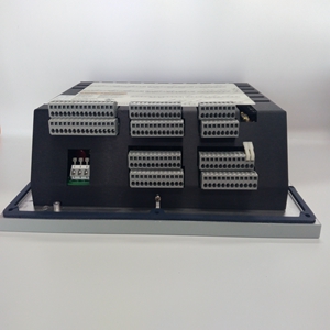
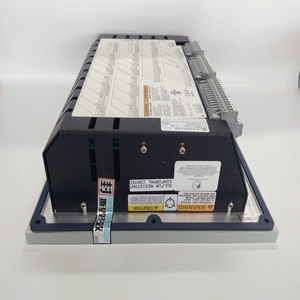
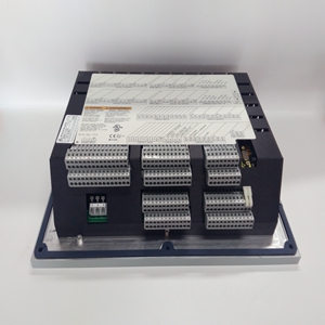
also tells this module in which rate group each channel is to run, as well as any special information (such as the type of thermocouple in the case of a thermocouple module). At run time, the CPU then periodically broadcasts a "key" to all I/O cards, telling them which rate groups are to be updated at that time. Through this initialization/key broadcast system, each I/O module handles its own rate-group scheduling with minimal CPU intervention. These smart I/O modules also have on-card on-line fault detection and automatic calibration/compensation. Each input channel has its own precision voltage reference. Once per minute, while not reading inputs, the on-board microcontroller reads this reference. The microcontroller then uses this data read from the voltage reference for both fault detection and automatic temperature compensation/calibration. Limits have been set for the expected readings when the on-board microcontroller reads each voltage reference. If the reading obtained is outside these limits, the system determines that the input channel, A/D converter, or the channel's precision-voltage reference is not functioning properly. If this happens, the microcontroller flags that channel as having a fault condition. The CPU will then take whatever action the application engineer has provided for in the application program. A smart output module monitors the output voltage or current of each channel and alerts the system if a fault is detected. Each I/O module has a fuse on it. This fuse is visible and can be changed through a cutout in the plastic cover of the module. If the fuse is blown, replace it with a fuse of the same type and size. Do not apply power to the unit until all the cables are connected. If you have the unit powered on before the cables are connected, you can blow the fuses on the output modules when the bare ends of the cables short together. MicroNet Simplex & MicroNet Plus Manual 26166V2 10 Woodward 10.2—Two Channel Actuator Controller 10.2.1—Module Description Figure 10-3 is a block diagram of the two-channel actuator controller module. Each channel controls an integrating or proportional, hydromechanical or pneumatic actuator. Each actuator may have up to two position feedback devices. There are several versions available, and the module part number indicates the module's maximum output current capability. A MicroNet lowdensity discrete (gray) cable must be used with this module. Do not use an analog (black) cable. Figure 10-1—Two Channel Actuator Controller Module 10.2.2—Module Specification General: Number of Channels 2 Actuator Type Proportional or integrating, hydromechanical or pneumatic actuators Power requirements +5 V @ 0.5 A, +24 V @ 1 A
相关产品


