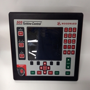
产品展示
联系我们
联系人:陈柳铭
手机:15579209656
电话:
Q Q:3136378118
邮箱:3136378118@qq.com
地址:江西省九江市瑞昌市东益路23号赛湖农商城401号
8915-861
3161调速器的示意图如图3-1所示
调速器先导阀需要增加燃油。3161调速器有一个独立的供油装置(约2.3 US qt/2.2 L)。机油从
驱动轴旋转时摆线泵吸入侧至压力侧
由原动机驱动。泵压力调节在大约100 psi(690
kPa)通过蓄能器弹簧和活塞。随着压力的增加
蓄能器活塞在气缸中向上移动,直到达到100 psi(690 kPa)。
此时,活塞中的排气口被打开,泵压力为
受监管。
蓄能器产生的压力决定了
州长。泵压力也用于安装在上的辅助设备
封面。
速度设置增加
顺时针(CW)旋转速度设定轴可增加
州长。(高速止动螺钉限制
调速器。)当速度设定轴旋转时,速度设定杆推动
放下连接到调速器插头的浮动杆。向下的
减速器塞上的压力压缩减速器弹簧并克服
球头飞锤降低球头先导阀的离心力
柱塞(pvp),增加调速器的速度设置。
当pvp降低时,压力油在动力活塞下方移动,使其
向上移动,提起端子杆并朝
增加方向。甚至在原动机达到新的设定速度之前,
补偿系统开始重新调整pvp的中心位置。随着动力活塞的移动
向上,动力活塞顶部的机油被挤出到缓冲活塞和
pvp上补偿用地的下侧。二者的效力变化
缓冲弹簧往往会阻止缓冲活塞的移动,从而导致
缓冲活塞上侧的油压较高,该压力为
传输到pvp补偿地的底部。在
补偿地两侧的压力产生一种作用力
将pvp推回其中心位置。
通过针阀节流孔的机油泄漏平衡了上述压力
并使缓冲活塞重新居中
在速度变化期间。当压力高于和低于补偿时
land变为相等时,缓冲弹簧将缓冲活塞返回到其中心位置
位置
速度设置降低
逆时针(CCW)旋转速度设定轴可降低速度
调速器的设置(低速止动螺钉限制
州长)。当速度设定轴逆时针旋转时,速度
移除浮动杆上的设定杆并降低压缩
从减速器弹簧。飞锤产生的离心力提升球头
先导阀柱塞(pvp),打开旋转衬套中的控制端口。
动力活塞下的控制油现在排放到油底壳,从而允许动力活塞
向下移动。输出轴沿下降方向旋转,速度
原动机转速降低。然后,薪酬体系带来
调速器处于稳定控制之下。


The schematic arrangement of the 3161 governor is shown in Figure 3-1, with the governor pilot valve calling for increased fuel. The 3161 governor has a selfcontained oil supply (approximately 2.3 US qt/2.2 L). The oil passes from the suction side to the pressure side of the gerotor pump as the drive shaft is rotated by the prime mover. Pump pressure is regulated at approximately 100 psi (690 kPa) by the accumulator spring and piston. As the pressure increases, the accumulator piston moves up in the cylinder until 100 psi (690 kPa) is obtained. At this time, bleed ports in the piston are uncovered, and pump pressure is regulated. The pressure generated by the accumulator, determines the work capabilities of the governor. Pump pressure is also used for the auxiliary devices installed on the cover. Increase in Speed Setting Rotating the speed setting shaft clockwise (CW) increases the speed setting of the governor. (The high speed stop screw limits the high speed setting of the governor.) As the speed setting shaft rotates, the speed setting lever pushes down on the floating lever which is attached to the speeder plug. The downward pressure on the speeder plug compresses the speeder spring and overcomes the centrifugal force of the ballhead flyweights to lower the ball-head pilot valve plunger (pvp), increasing speed setting of the governor. When the pvp is lowered, pressure oil moves under the power piston causing it to move up, lifting the terminal lever and rotating the output shaft towards the increase direction. Even before the prime mover has reached the new set speed, the compensation system starts to re-center the pvp. As the power piston moves up, the oil on top of the power piston is forced out to the buffer piston and to the lower side of the compensation land on the pvp. The change in force on the two buffer springs tends to resist the movement of the buffer piston, causing a slightly higher oil pressure on the upper side of the buffer piston, with this pressure being transmitted to the bottom side of the pvp compensation land. The difference in pressures on the two sides of the compensation land produce a force which acts to push the pvp back to its centered position. Leakage, of oil through the needle valve orifice equalizes the pressures above and below the compensation land, and allows the buffer piston to re-center during speed changes. As the pressures above and below the compensation land become equal, the buffer springs return the buffer piston to its centered position. Decrease in Speed Setting Rotating the speed setting shaft counterclockwise (CCW) decreases the speed setting of the governor (the low speed stop screw limits the low speed setting of the governor). As the speed setting shaft rotates CCW, the force of the speed setting lever on the floating lever is removed and the compression is reduced from the speeder spring. Centrifugal force from the flyweights raises the ballhead pilot valve plunger (pvp), uncovering the control port in the rotating bushing. Control oil under the power piston now drains to sump, allowing the power piston to move down. The output shaft rotates in the decrease direction, and the speed (rpm) of the prime mover is decreased. The compensation system then brings the governor under stable control.
相关产品


