产品展示
联系我们
联系人:陈柳铭
手机:15579209656
电话:
Q Q:3136378118
邮箱:3136378118@qq.com
地址:江西省九江市瑞昌市东益路23号赛湖农商城401号


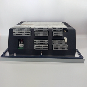
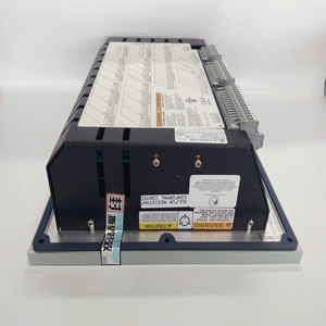
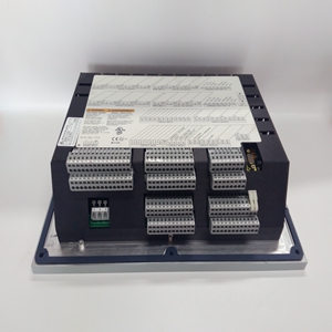
8270-768
原动机启动且调速器控制后,打开
针阀(逆时针转动),直到调速器运行变得不稳定。然后
缓慢关闭针阀(顺时针转动),直到调速器稳定。
让调速器和原动机达到工作温度。作为
调速器预热,可能会变得不稳定。如果是,缓慢关闭针阀
直到调速器稳定下来。不要完全关闭针阀。这
可能导致启动或甩负荷时超速过度。
3161调速器手册03101
6伍德沃德
第三章。
操作原理
组件说明
摆线转子油泵摆线转子油泵位于调速器底座中。
泵的内转子由驱动轴中的销驱动,并承载
外转子周围啮合,将机油泵送至蓄能器活塞。
蓄能器—由活塞和弹簧组成的单个蓄能器起到
用于油泵的安全阀,并为快速
伺服运动。机油由调速器泵泵送至蓄能器
蓄能器弹簧压缩时压力升高。当
压力升至预定水平,机油通过
活塞壁中的卸压口。
动力活塞动力活塞通过连杆与输出轴相连
操纵杆总成。动力活塞底部设计有大面积
顶部有一小块区域(差速器活塞)。压力小幅度增加
活塞的大面积将使活塞向上移动,导致输出轴旋转
在“增加”方向。只有当机油在以下位置时,活塞才能向下移动
活塞被释放到油底壳。流入或流出动力活塞底部的机油
由球头先导阀和球头先导阀衬套调节。
先导阀系统
先导阀系统由两个部件组成,球头先导阀
(旋转)衬套和球头先导阀柱塞。衬套旋转
相对于先导阀柱塞,减少两部分之间的摩擦。这个
先导阀柱塞的控制凸台调节通过
球头衬套的控制端口。
降低先导阀柱塞时,高压油流过
衬套控制端口,至动力活塞底侧和活塞
向上移动。当先导阀柱塞升起时,来自
动力活塞释放到油底壳,活塞顶部的压力较高
向下移动活塞。当原动机在稳态运行时
先导阀柱塞的控制凸台覆盖球头衬套中的端口
动力活塞不移动。先导阀柱塞的移动为
由球头组件控制。
球头总成
球头系统包括球头、飞锤、速度器弹簧、推力
轴承和调速器螺塞。球头作为先导阀衬套的一部分
由驱动联轴器和驱动轴旋转。
当球头旋转时,离心力使飞锤转动
表面的同时,调速器弹簧迫使止推轴承向下
在飞锤脚趾上,与飞锤的离心力相反。推
减速器插头向下会增加减速器上的向下压力
弹簧,调速器转速设定值增加。然后原动机运行
以更高的速度在飞锤上产生更大的离心力
克服调速器弹簧力并重新平衡系统。
After the prime mover has started and the governor is controlling, open the needle valve (turn it CCW) until governor operation just becomes unstable. Then slowly close the needle valve (turn it CW) until the governor just becomes stable. Allow the governor and prime mover to reach operating temperature. As the governor warms up, it may become unstable. If so, slowly close the needle valve until the governor just becomes stable. DO NOT fully close needle valve. This may cause excessive overspeed on start-up or load rejection. 3161 Governor Manual 03101 6 Woodward Chapter 3. Principles of Operation Component Description Gerotor Oil Pump—The gerotor oil pump is located in the base of the governor. The inner rotor of the pump is driven by a pin in the drive shaft, and carries the outer rotor around in mesh, pumping oil to the accumulator piston. Accumulator—A single accumulator, consisting of a piston and spring, acts as a relief valve for the oil pump and provides a reservoir of high pressure oil for quick servo movement. Oil is pumped to the accumulator by the governor pump, with pressure increasing as the accumulator spring is compressed. When the pressure builds to the predetermined level, oil is released back to sump through relief ports in the piston wall. Power Piston—The power piston is attached to the output shaft by a link and lever assembly. The power piston is designed with a large area on the bottom and a small area on top (differential piston). A small pressure increase on the large area of the piston will move the piston up, causing the output shaft to rotate in the “increase” direction. The piston can move down only when oil under the piston is released to sump. Oil to or from the bottom of the power piston is regulated by the ballhead pilot valve and ballhead pilot valve bushing. Pilot Valve System The pilot valve system consists of two components, the ballhead pilot valve (rotating) bushing, and the ballhead pilot valve plunger. The bushing is rotated relative to the pilot valve plunger to reduce friction between the two parts. The control land of the pilot valve plunger regulates the flow of control oil through the control ports of the ballhead bushing. When the pilot valve plunger is lowered, high pressure oil moves through the control port of the bushing, to the bottom side of the power piston, and the piston moves up. When the pilot valve plunger is raised, the oil from the bottom of the power piston is released to sump, and the higher pressure on top of the piston moves the piston down. When the prime mover is running at steady state, the control land of the pilot valve plunger covers the porting in the ballhead bushing and the power piston does not move. The movement of the pilot valve plunger is controlled by the ballhead assembly. Ballhead Assembly The ballhead system consists of a ballhead, fly-weights, speeder spring, thrust bearing, and speeder plug. The ballhead, as part of the pilot valve bushing, is rotated by the drive coupling and drive shaft. As the ballhead rotates, the centrifugal force causes the flyweights to pivot outward. At the same time, the speeder spring is forcing the thrust bearing down on the flyweight toes opposing the centrifugal force of the flyweights. Pushing down on the speeder plug increases the downward pressure on the speeder spring, and the governor speed setting is increased. The prime mover then runs at a higher speed to produce a higher centrifugal force on the flyweights to overcome the speeder spring force and rebalance the system.
相关产品


