产品展示
联系我们
联系人:陈柳铭
手机:15579209656
电话:
Q Q:3136378118
邮箱:3136378118@qq.com
地址:江西省九江市瑞昌市东益路23号赛湖农商城401号
1622-294-10
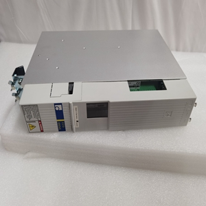
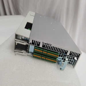
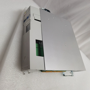
11 X16编程接口(COM)12 X10串行接口(PROG)13用于接地的插入螺栓14 X7E以太网接口(可选)图12-1:PPC-R22.1 PPC-R是一种IP 20设计的小尺寸大容量控制器。PPC-R是一个通用平台,提供运动控制(MC)或PLC功能,这取决于应用程序和软件。根据Indra‐mat标准(SIS=串行Indramat接口),控件上的两个可用接口完全连接。数据类型传输(功能)仅由应用程序(RS232/RS422/RS485)选择。由一个或多个RMB02.2-04组成的模块托架系统用于安装PPC\R。双托架RMB02.2-02只能用作安装托架。载体只能用于固定PPC-R,无法控制RECO模块。也不可能通过背板耦合多个PPC-R。PPC-R多可操作15个以上的输入/输出模块(RME02.2…、RMA02.2…或RMC02.2…)在这个载体系统中。根据应用情况,PPC-R配有PC/104模块,例如用于开放式现场总线接口,如Interbus、Profibus等。12.2操作和错误显示符号,LED显示屏描述测量以太网上的LED H3 LED激活(发送和接收活动)以太网链路有效-LED关闭以太网未激活检查以太网连接H1-四个数字诊断显示屏的相关性取决于配置-图12-1:前面板上用于操作和错误显示的LED 13错误原因和消除典型应用错误安装情况未知。14维护控制装置免维护。


11 X16 programming interface (COM) 12 X10 serial interface (PROG) 13 Insert bolt for ground connection 14 X7E Ethernet interface (optional) Fig.12-1: PPC-R22.1 The PPC-R is a small size high-capacity control in IP 20 design. The PPC-R is a universal platform that provides Motion Control (MC) or PLC functionality that depend‐ ing on the application and software. The two interfaces available on the control are fully connected according to the Indra‐ mat standard (SIS = Serial Indramat Interface). The data type transfer (function) is only selected by the application (RS232/RS422/RS485). A module carrier system consisting of one or several RMB02.2-04 are used to mount the PPC_R. The dual carrier RMB02.2-02 can only be used as mounting carrier. The carrier can only be used to fix the PPC-R, controlling RECO modules is not possible. It is also not possible to couple several PPC-R via a back plane. The PPC-R can operate up to 15 more I/O modules (RME02.2..., RMA02.2... or RMC02.2...) in this carrier system. Depending on the application, the PPC-R is equipped with PC/104 modules, e.g. for open field bus interfaces such as Interbus, Profibus etc. 12.2 Operating and Error Display Symbol, LED Display Description Measure LED H3 LED on Ethernet active (sending and receiving activity) The Ethernet link is valid - LED off Ethernet not active Check Ethernet connection H1 - The relevance of the four-dig‐ it diagnostic display depends on the configuration - Fig.12-1: LED for operating and error display on the front panel 13 Error Causes and Elimination Typical application errors upon the installation are not known. 14 Maintenance The control is maintenance-free.
相关产品


