产品展示
联系我们
联系人:陈柳铭
手机:15579209656
电话:
Q Q:3136378118
邮箱:3136378118@qq.com
地址:江西省九江市瑞昌市东益路23号赛湖农商城401号


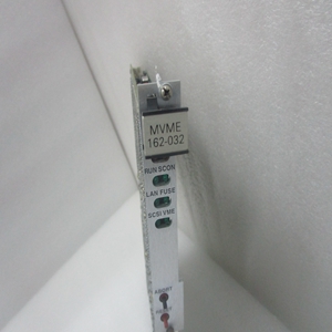
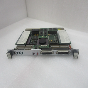
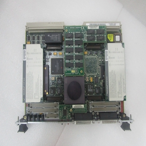
MVME2700-1461
模块安装在安装了EPROM和IndustryPack并正确配置了标头的情况下,按照以下步骤在VME机箱中安装MVME:1。关闭所有设备电源,并断开电源线与交流电源的连接。注意:通电时插入或拆卸模块可能会损坏模块组件!警告:此设备中存在可能导致死亡的危险电压。在搬运、测试和调整时要格外小心。2、按照设备用户手册中的说明卸下机箱盖。3、从要安装MVME的卡槽中卸下填充板如果要将MVME用作系统控制器,它必须占用左侧的卡插槽(插槽1)。系统控制器必须位于插槽1中,以正确启动总线授权菊花链,并确保IACK菊花链驱动程序的正确操作如果不打算将MVME用作系统控制器,它可能会占用任何未使用的双高卡插槽。4、将MVME滑入所选卡槽。确保模块正确安装在背板上的P1和P2接头中。不要损坏或弯曲接头针脚。5、使用提供的螺钉将MVME固定在机箱中,与横向安装导轨保持良好接触,以尽量减少射频发射。将MVME712系列转换模块安装在VME机箱的前部或后部。(要安装具有双宽前面板的MVME712M,您可能需要移动机箱中的其他模块。)7、在机箱背板上,从MVME占用的卡插槽的标头上卸下中断确认(IACK)和总线授权(BG)跳线。
Module Installation With EPROM and IndustryPacks installed and headers properly configured, proceed as follows to install the MVME in the VME chassis: 1. Turn all equipment power OFF and disconnect the power cable from the AC power source. Caution Inserting or removing modules while power is applied could result in damage to module components. ! WARNING Dangerous voltages, capable of causing death, are present in this equipment. Use extreme caution when handling, testing, and adjusting. 2. Remove the chassis cover as instructed in the user’s manual for the equipment. 3. Remove the filler panel from the card slot where you are going to install the MVME. – If you intend to use the MVME as system controller, it must occupy the leftmost card slot (slot 1). The system controller must be in slot 1 to correctly initiate the bus-grant daisy-chain and to ensure proper operation of the IACK daisy-chain driver. – If you do not intend to use the MVME as system controller, it can occupy any unused double-height card slot. 4. Slide the MVME into the selected card slot. Be sure the module is seated properly in the P1 and P2 connectors on the backplane. Do not damage or bend connector pins. 5. Secure the MVME in the chassis with the screws provided, making good contact with the transverse mounting rails to minimize RF emissions. 6. Install the MVME712 series transition module in the front or the rear of the VME chassis. (To install an MVME712M, which has a double-wide front panel, you may need to shift other modules in the chassis.) 7. On the chassis backplane, remove the INTERRUPT ACKNOWLEDGE (IACK) and BUS GRANT (BG) jumpers from the header for the card slot occupied by the MVME.
相关产品


