产品展示
联系我们
联系人:陈柳铭
手机:15579209656
电话:
Q Q:3136378118
邮箱:3136378118@qq.com
地址:江西省九江市瑞昌市东益路23号赛湖农商城401号


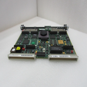
MVME224A-3
安装新SIM卡
1、观察SIM卡接头J1和
接头J10。转动SIM卡,使钥匙对齐并放置
将其轻轻地安装在连接器J10上,对准SIM卡拐角处的安装孔
与上的对峙相匹配。
2、轻按SIM卡顶部,将其固定在连接器上。如果SIM卡有
不要用温和的压力坐好,重新检查方向。如果SIM卡连接器
如果方向不正确,安装孔将与
僵局。
警告:如果SIM卡方向不正确,请不要试图强行打开SIM卡。
3、放置两个4-40 x 3
/之前使用的16“十字头螺钉
已将(或新SIM卡附带的)插入两个相对的角安装孔中。将其拧入防区,但不要
过紧。
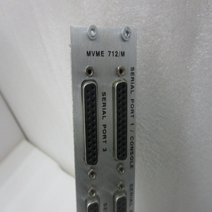
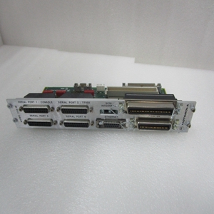
各种串行通信中的信号关系和信号连接
端口A和B的可用配置如图2-3、2-4所示,
和2-5。
系统控制器选择收割台(J1)
出厂时配置为VMEbus系统控制器(即
跨接导线安装在收割台J1的针脚1和2之间。如果出现以下情况,请拆下J1跨接导线
不是系统控制器。请注意,当
用作系统控制器,SCON LED亮起。
注:对于无可选VMEbus接口的s(即。,
无VMEchip2),可安装或拆除跳线
不影响正常运行。
J1
2.
1.
2.
1.
J1
系统控制器(出厂配置)非系统控制器
Installation of New SIM 1. Observe the orientation of the connector keys on SIM connector J1 and connector J10. Turn the SIM so that the keys line up and place it gently on connector J10, aligning the mounting holes at the SIM corners with the matching standoffs on the . 2. Gently press the top of the SIM to seat it on the connector. If the SIM does not seat with gentle pressure, recheck the orientation. If the SIM connector is oriented incorrectly, the mounting holes will not line up with the standoffs. Caution Do not attempt to force the SIM on if it is oriented incorrectly. 3. Place the two 4-40 x 3 /16” Phillips-head screws that you previously removed (or that were supplied with the new SIM) into the two oppositecorner mounting holes. Screw them into the standoffs but do not overtighten them. The signal relationships and signal connections in the various serial configurations available for ports A and B are illustrated in Figures 2-3, 2-4, and 2-5. System Controller Select Header (J1) The is factory-configured as a VMEbus system controller (i.e., a jumper is installed across pins 1 and 2 of header J1). Remove the J1 jumper if the is not to be the system controller. Note that when the is functioning as system controller, the SCON LED is turned on. Note For s without the optional VMEbus interface (i.e., no VMEchip2), the jumper may be installed or removed without affecting normal operation. J1 2 1 2 1 J1 System Controller (factory configuration) Not System Controller
相关产品


